Search in The Electromania's Blog

Sunday 13 December 2015

Home built IR Remote receiver or Demodulator using Phototransistor - working with Arduino Due


My IR receiver module from Banggood bangged after first run - it just ceased working. The next new one will come a months later, but the show must go on....

So thought of trying custom built temporary IR Receiver Demodulator module using available photo-transistor BPW 77NB and standard NPN amplifier transistor PN2222A. 
Note that in circuit diagram i have shown LEDs connected to pin 5,6,7 only, but practically i have connected one more bi-color LED to pin 3 and 4. This was just as fun for my kid.


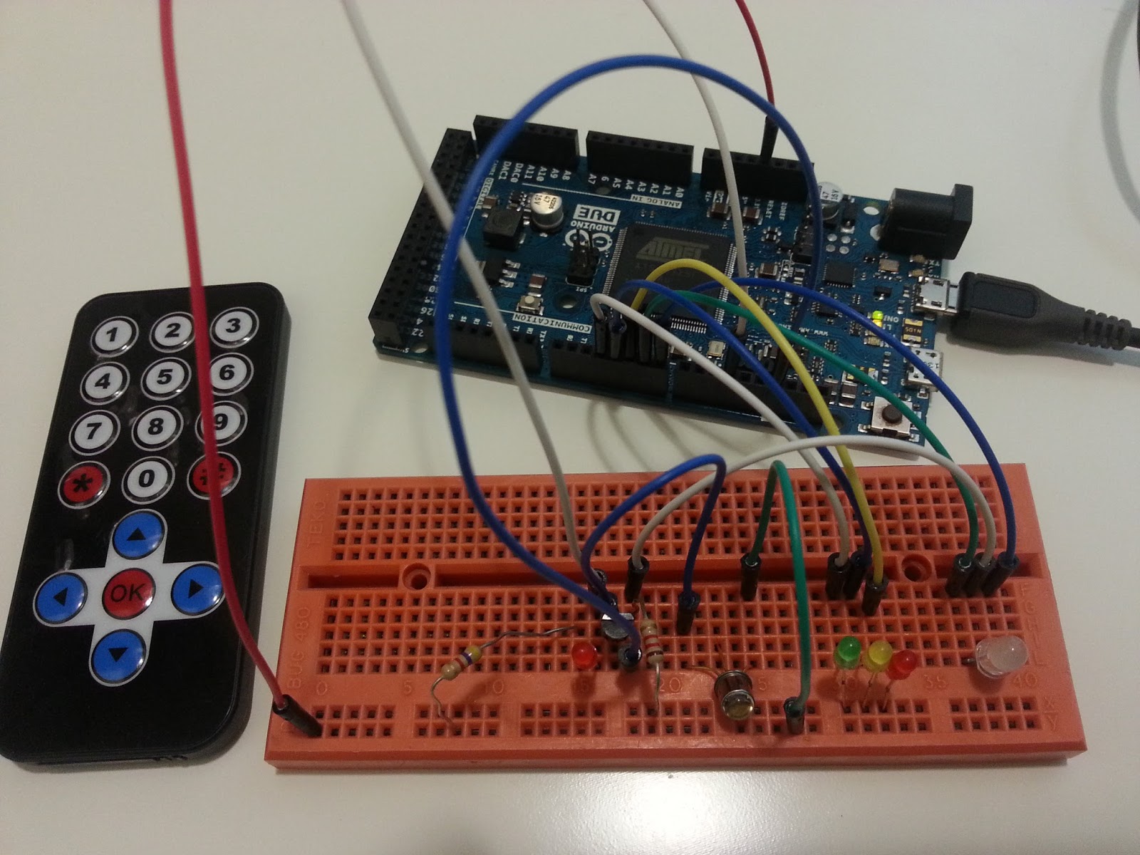
And to my surprise it worked :)


Final sketch is given below or is available on my GitHub page here..
https://github.com/Electromania/Arduino-Due/blob/master/Quick-Projects/IR%20Remote%20kit%20Arduino%20Due%20using%20Phototransistor 

Currently, the range of IR receiving was only upto 12-15 inches, may be by fine tuning the gain of amplifier transistor or photodetector, it can be increased. I am not an electronics engg... no idea how to do it. Any ideas or suggestions are most welcomed. 

Till then... have fun.... the show must go on... :)

-Original Library from - https://github.com/enternoescape/Arduino-IRremote-Due
-Initial circuit of BPW77NB from-
https://www.youtube.com/watch?v=XsHnvvSzr1M
-Sketch modified by Electromania Dec 2015 

Sunday 6 December 2015

ESP8266 ESP-12E nodemcu 1.0 Getting started with Esplorer - Loading latest firmware - Lua sketch for onboard and external LED blinking


We will be connecting the NodeMCU to PC, Installing Esplorer IDE, Uploading Latest firmware and a test sketch to blink onboard LED and externally connected LED.


*Programming IDE - esplorer available at http://esp8266.ru/esplorer/  or   https://github.com/4refr0nt/ESPlorer  

*Firmware flasher to update firmware- https://github.com/nodemcu/nodemcu-flasher/blob/master/Win64/Release/ESP8266Flasher.exe 

*Firmware- https://github.com/nodemcu/nodemcu-firmware/releases 

I have used -  nodemcu_float_0.9.6-dev_20150704.bin firmware

*Pin configuration of nodemcu V 1.0: https://github.com/nodemcu/nodemcu-devkit-v1.0

NOTEJust plug USB cable between your PC and Nodemcu - no additional hardware modifications or power supply are required.

Unlike other ESP8266 modules,
while flashing firmware, loading sketches, running in normal operations, NO NEED of changing any pin configuration (e.g. pulling high or low pin 0 ,2 etc), NodeMCU E12 dev kit does everything internally. 


The final code to test onboard LED at gpio0 and externally connected LED ,red, at gpio1-pin D1. 

just copy and paste following code in esplorer scripts window and press Send to ESP
--/////////////////////////////////////////Start of Code//////////////////////////////////////////////////////////////
function blinktest()
    for i = 1, 10, 1 do       -- blink LED 50 times
    gpio.write(0, gpio.HIGH)  -- note onboard Blue LED is OFF when GPIO0 is high.
    gpio.write(1, gpio.HIGH)  -- RED LED is ON when GPIO1 is high.
     print("Red ON ",i)
    tmr.delay(500000) -- wait for 0.5 sec = 500 000 micro-sec
    gpio.write(0, gpio.LOW)  -- note onboard Blue LED is ON when GPIO0 is Low.
    gpio.write(1, gpio.LOW)  -- -- RED LED is OFF when GPIO1 is low.
      print("Red OFF ",i)
    i = i + 1;
    tmr.delay(500000)  -- wait for 0.5 sec = 500 000 micro-sec
    end
end

function testnodemcu()

blinktest()
tmr.delay(10000)  -- wait for 10micorsec
print("Congratulations for your first successfull NODEMCU E12 LED blink Test")
gpio.write(0, gpio.HIGH)  -- swtich OFF Blue LED at the end
end


testnodemcu()  -- function to run the test script
--///////////////////END of CODE///////////////////////////////


Contact Electromania

Name

Email *

Message *